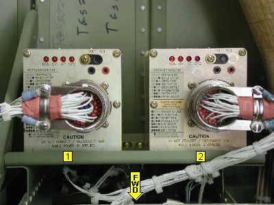
|
|
|
PINS
|
Functions
A
|
28VDC start command input from Left
Start PC Board (NZ011)
|
J
|
28VDC output to left start PC board
for control of the Left Start Relay (KZ007)
|
L
|
28VDC start command output to left
start PC board if engine speed is less than 40% N2.
|
M and m
|
Input from Left Ground Fault
Transformers (UT005 and UZ005).
|
s
|
28VDC input from L START Circuit
Breaker (CB61)
|
W
|
|
Variable VDC input from Left Starter/Generator (SG1) compensation windings (terminal D) for control of the field weakening circuit.
X and Y
|
Input from left starter generator
magnetic pickup.
|
y
|
|
28VDC input from LH GENERATOR Circuit Breaker (HT017) for starter generator field excitation.
AA
|
Variable VDC output to starter
generator A terminal for field winding excitation.
|
DD
|
Airframe ground input from starter
generator E- terminal for GCU field winding clipping diode.
|
FF
|
Airframe ground input from starter
generator E- terminal for voltage sensing.
|
|


